|
Spindle Tool Kit:
Removal tool with 8x1 mm stud
5/8-inch x 12 nut
Stepped steel washer
Two steel sleeves: 1 5/16 and 4 3/4 inches
|
Bearing Installation
Kit:
Two aluminum blocks
Two steel washers for spindle bolts
Six 0.093" shims
Six 0.020" shims
|
Tools Needed:
Circlip pliers (i.d. type)
Two 5/8-inch open-end wrenches
3/8-inch (approx.) aluminum dowel or drift
Two 14-mm open-end wrenches
Bench vise
|
 |
Spindle Removal:
Remove Crankarm bolts, if present.
Run the 5/8-inch nut to the head of the removal
tool.
Put the stepped steel washer on the tool.
Put the 4 3/4-inch sleeve on the tool.
Thread the tool into the spindle and tighten.
Tighten the nut against the washer and sleeve.
Hold the 5/8-inch nut and turn the spindle tool
counterclockwise. The sleeve will press against
the bearing and extract the spindle.

|
Spindle Installation:
Make sure the bearing spacer inside the BB shell
is not cocked or displaced.
Run the 5/8-inch nut to the head of the spindle
tool. Put the stepped steel washer on the tool.
Put the 1 5/16-inch sleeve on the tool.
Push the tool through the bottom bracket, leaving
bearings and spacers intact.
Thread the spindle onto the tool and tighten. Do
not lubricate the surface of the spindle.
Tighten the but against the sleeve.
Hold the 5/8-inch nut and turn the spindle tool
counterclockwise. The sleeve will press against
the bearing and pull the spindle into place.
Adjust the lateral position of the spindle with
the short steel sleeve.

|
Bearing Removal:
Remove the spindle.
Remove the bearing circlips.
Using a 3/8-inch dowel
(approximate size), push the bearing spacer down
out of the way and punch out the bearings evenly.
Be careful not to damage the bearing spacer,
clear Lexan seal spacer, or grease ports inside
the shell.

|
Bearing Installation:
Remove and clean the seals. Remove the metal
bearing spacer. Do not attempt to remove the
clear Lexan seal spacer.
Reinstall the two black WTB Grease Guard seals
(one on each side) with the writing on the inside
against the Lexan spacer.
Reinstall the two white spacers (one on each
side) with the gaps facing the Grease Guard
ports.
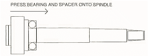
Using a vise, press the bearing spacer onto the
drive side of the spindle, flush with the spindle
end. Do not lubricate the spindle or spacer
before installation.

Using the aluminum block, one
bearing (open side facing in), and the
appropriate shims (if necessary; see table),
press the bearing spacer and the bearing the rest
of the way onto the spindle. This will center the
spacer.

Place a 3/8-inch washer onto the aluminum block
(and shims, if present) and install the 14-mm
spindle bolt. Snug the bolt by hand.
Slide the spindle into the shell from the drive
side. Be careful not to bend back the lips of the
black grease seals.
Put the other bearing onto the spindle, open end
facing in. Place the aluminum block onto the
bearing and presss the bearing into the shell by
hand to start it into place. Then install shims,
if necessary (see table), a 3/8-inch washer, and
the spindle bolt.

With two 14-mm wrienches, hold the drive-side
spindle bolt and tighten the left spindle bolt to
press the bearings into place.
Remove the bolts, shims, washers, and blocks.
Replace the circlips. Grease the bearings.
|
Bearing Installation Table
|
Spindle Length
|
Block and Shims
|
| 113 mm |
Aluminum block only |
| 119 mm |
Aluminum block
1x0.093"
1x0.020" |
| 122.5 mm |
Aluminum block
2x0.093" |
| 125 mm |
Aluminum block
2x0.093"
3x0.020" |
| 130 mm |
Aluminum block
3x0.093"
3x0.020" |
|


